Skew Tool
Table of contents:
Introduction
Skew
Skew a region
Skew a profile
Advanced Settings
Tips & Tricks
Hello!
Welcome to the article, in which we are going to learn about SelfCAD's 3D modeling tool called Skew. I am going to explain all of its ins and outs and present its general applications. On top of that, I will share a few Tips and Tricks that you could use with Deformations.
Skew is one of the basic Deformation tools available in SelfCAD, and you will find it in the main Toolbar, in the Deform drop-down list. As its name suggests, it allows you to deform selected figures or their regions by skewing them to the sides.
Deform is a unique category because tools in it rely heavily on the level of the detail of the objects. It means that by increasing their Resolution, you will achieve a much smoother and detailed deformation. On top of that, with the Advanced Settings such as the Origin and the Minimum Step Size, you can customize the Skew even further.
Follow this article to learn all about this tool!
Select the object
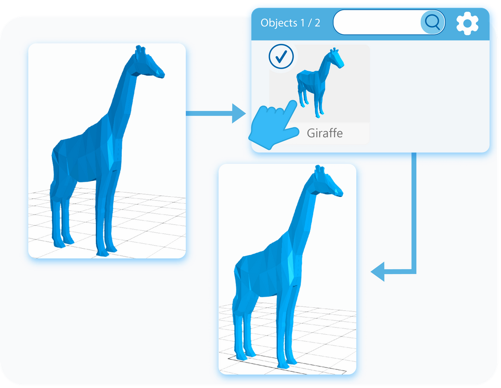
The first step of using any modeling tool is selecting the object on which you want to use it. You can select objects by either left-clicking on them in the workspace or by selecting them in the Object Management section, in the right-side panel. The second option has an in-built search engine, which is extremely useful when you are working with multiple objects.
Activate the tool
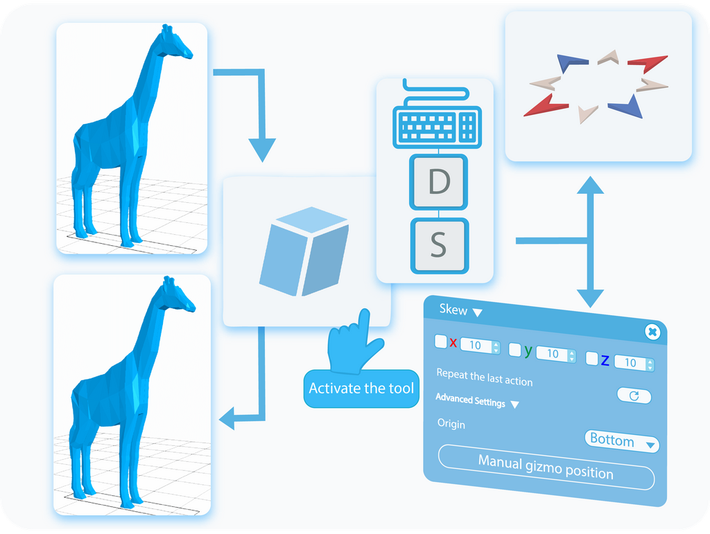
Once the object is selected, you can activate the Skew tool by selecting it from the Deform drop-down list, or use a shortcut, by pressing the ‘D+S’ combination on your keyboard. This way, you’ll open a Tool Setting Panel with all of the customizable options for this tool on the left side of your screen. Activating the Skew tool will also enable the Gizmo that you can use to Deform the object.
Skew
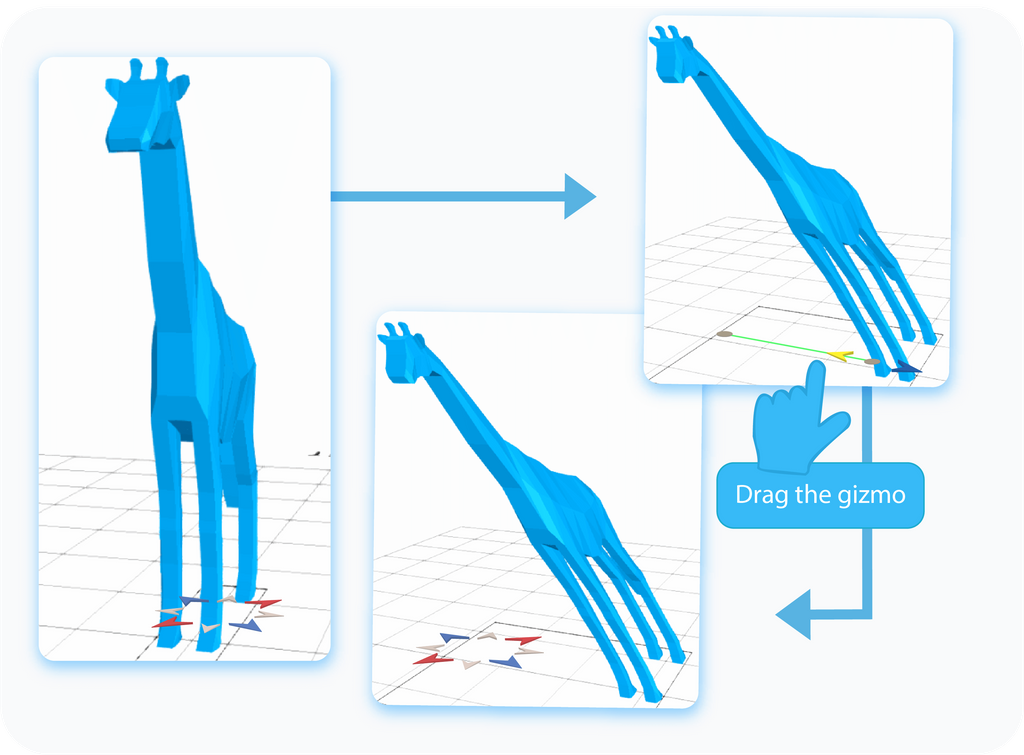
The first option to skew the selected object in SelfCAD is by dragging the Gizmo mentioned in the previous paragraph. As you can see, it points in different directions, which indicate in which dimension and in which way you can skew the object.
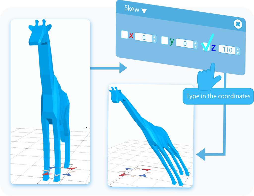
The second way to skew the object is by typing the exact values into the text boxes in the Tool Setting Panel. Furthermore, you can use the checkboxes to copy the same values between the text boxes. Each of them refers to one of the axes, whose position you can check on the 3D Coordinates Axis on the bottom right side of the grid.
Select a region
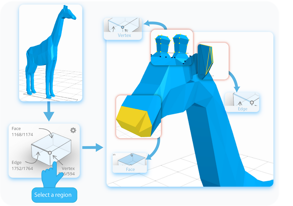
SelfCAD allows you to not only skew the object itself, but you can also skew some of its regions. To do so, you need to select them first. In the Right Side Panel, you will find an Interactive Rectangle, where you can enter one of the following selection modes: Face, Vertex, and Edge. Then, you can select the parts of the object that you want to skew.
Skew a region
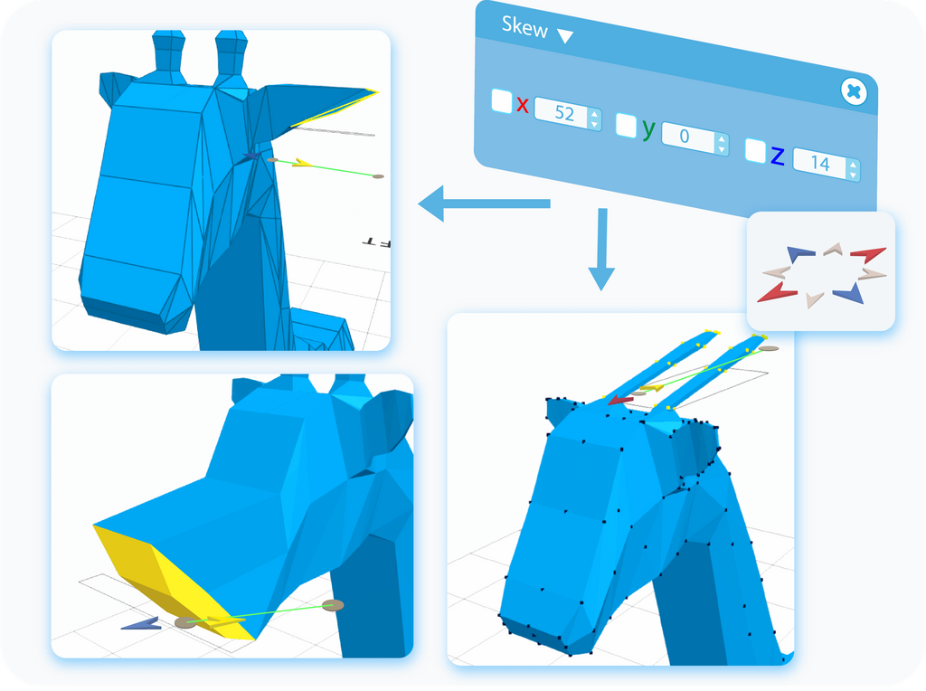
Skewing a region works exactly the same as skewing the object itself does. After selecting a region or regions that you want to skew, you can either drag them with the help of the Gizmo or type in the values into the text boxes, to skew the selected region to the typed value. Because of the nature of the tool, you are limited to skewing only vertical regions of the object.
Skew a profile
In SelfCAD, there is an option to Skew the Profiles as well, drawn with the help of the Freehand or 3D Sketch tools. The process is exactly the same as described above. After selecting the profile from the Object Management Panel, all you have to do is Skew it with either the Gizmo or by typing values directly into text-boxes. Of course, most profiles consist of multiple regions, which means that you can Skew them individually as well, as explained above. Just remember that depending on the position and rotation of the Profile, you will have to switch the Plane setting for this tool to work.
Origin
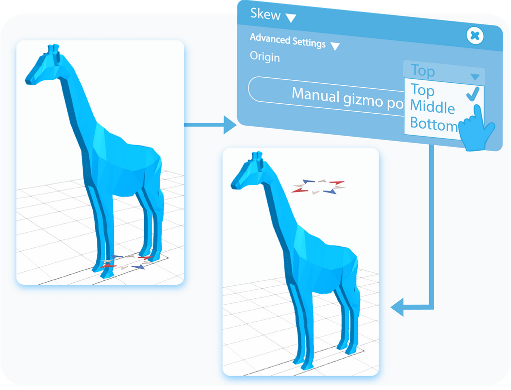
Within the Advanced Settings of the Skew tool, there is an option called Origin. Origin sets the position of the Gizmo. In practice, you can use it to set a point from which the object will skew. You can choose the point of Origin from the options available in the drop-down list.
Manual gizmo position
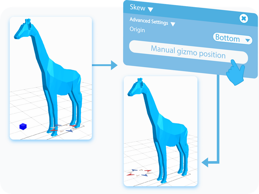
Manual gizmo position is an extension to the Origin feature with only a single difference. While Origin allows you to set the vertical position of the Gizmo, here, you can manually set its horizontal position to any place in the workspace.
Individual transformation
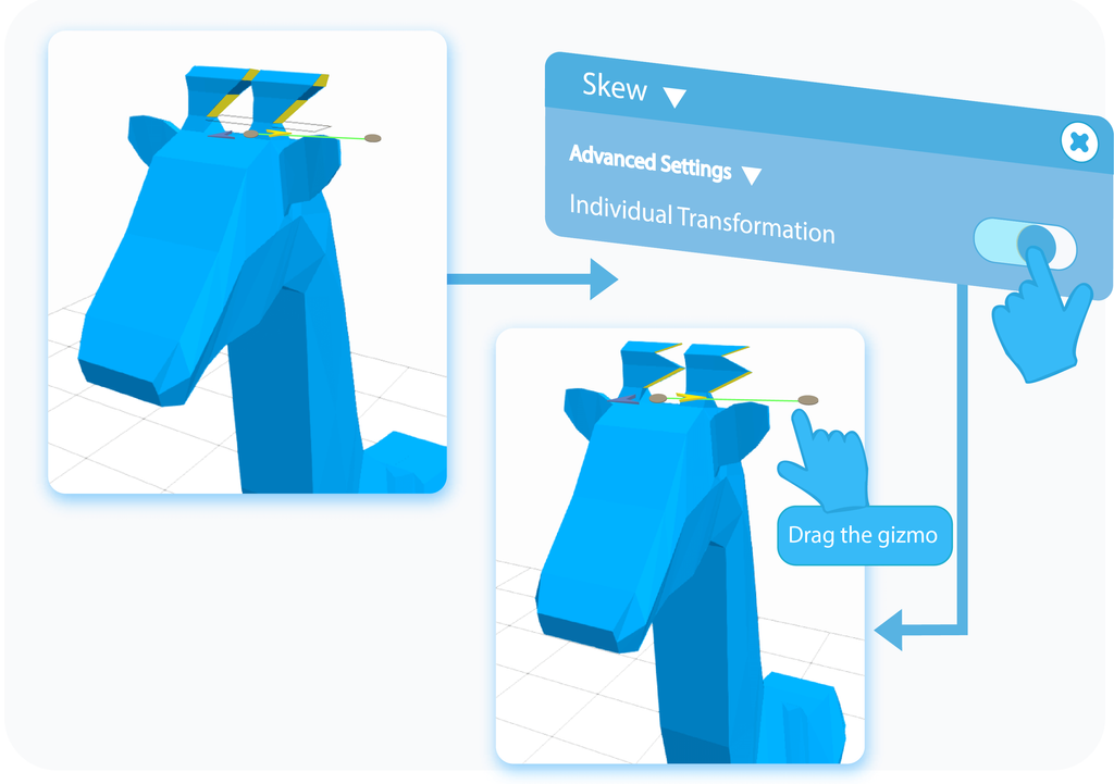
Individual Transformation is another feature available in the Advanced Settings of the Skew tool, and it is available only when you are skewing at least two separate Faces of the object. As the name suggests, by enabling this option, you will Skew selected parts independently from each other. Again, if you need a reminder on how to select a region, you can go back to previous paragraphs for a detailed explanation.
Minimum Step Size
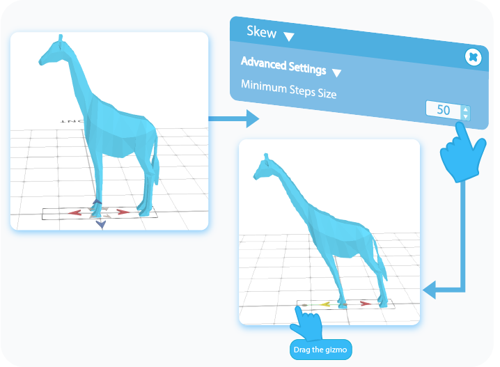
Minimum Step Size is one of the most useful features when it comes to precise modeling, and you have to operate on strict values. It locks the tool at a specified value, and it will skew the object by the multiplication of this value. For example, if you set this feature to 50, then you will be able to Skew the object for 50 units in any direction, which will be the first step. When you try to Skew it further, it will do so by another 50 and so on.
Viewports
You can use up to four Viewports to see the changes made to the model from different perspectives.
And that’s about it for the Skew tool. After reading this article, you should know the basics of the Skew tool and how to use it, know about its different applications and how to implement and customize its advanced settings. Of course, the graphics shown here were just examples, and using this tool on other shapes will give you slightly different effects, but its underlying principles will always stay the same.
That's all I have for you today. I wish you success in your future projects. See you, and stay tuned for more content to come!
Haven't tried SelfCAD yet? Register now, and try it out for free!

Do you want to learn 3D modeling? Check out our interactive tutorials.


