Basic 3D Shapes
Table of contents:
Introduction
Adding Shapes
Customizing Shapes
Additional Settings
Customizing Placement
Tips & Tricks
Let’s talk about the 3D Shapes tool. In this article, I'll explain everything you need to know about creating and customizing basic shapes in SelfCAD. 3D Shapes can be found in the main Toolbar, and as you can see, Shapes in this category have been divided into two sections: basic and advanced. I'm going to focus on the basic shapes here - simple geometrical figures. Because of their simplicity, the customization process behind them is very straightforward. That's why they all will be covered in this article.
Adding shapes
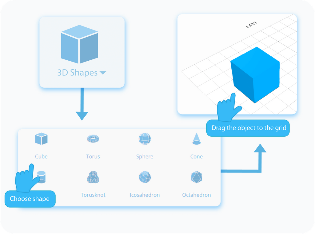
Let's start with adding Shapes to the workspace. There are two ways to do that. The first option is to simply select the shape you want to add from the drop-down list and drag it to any place on the grid. It's the quickest way to add shapes, but the downside of this method is that your shape will be created with its default 3D properties, and it will skip the customization process unique to the selected model.
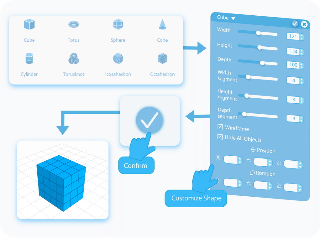
The second way to add Shapes to the workspace is by clicking on the chosen shape in the drop-down list. By doing so, you will open the Tool Settings panel on the left side of the screen, which will contain all of the unique settings available for the chosen shape. Contrary to the previous method, here you can customize your Shape even before it will be added to the grid. You can set here the properties such as size, detail, arc and fill, position, and rotation. It's important to note that once you finish this process, you won't be able to get back to those settings. Of course, you will still be able to modify your shapes with the help of other tools, but the settings explained in this article can be accessed only when adding new Shapes.
Size
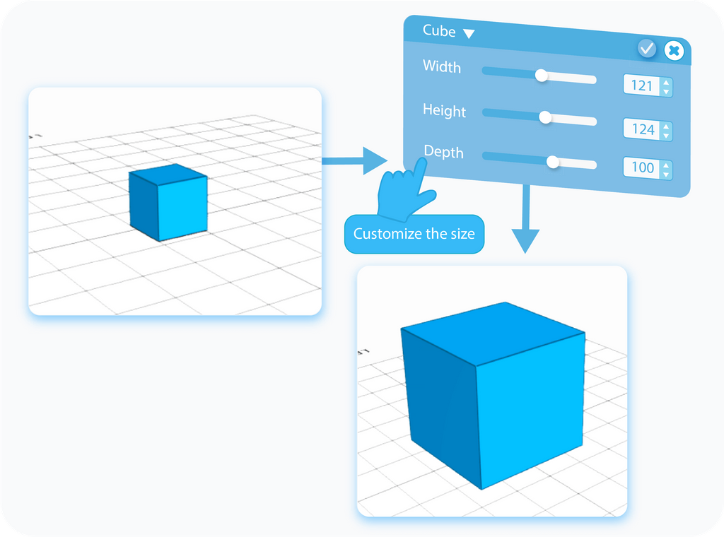
How big do you want your model to be? That's the question the Size setting is going to answer. The number and names of settings dedicated to the Size will differ between different 3D Shapes. Those based on circles, like spheres, cylinders, and so on, will have settings pertaining to the Radius of the object, while shape like a Cube will have settings of the Width, Depth, and Height. You can choose the object's dimensions by either moving the slider to manipulate the values or by typing the values directly into the textboxes. It's important to note that by typing the values, you are able to set the size of the object beyond what is possible with the slider; the reason is that the slider needs a finite point, while when typing, you are only restricted by the size of the grid.
Detail
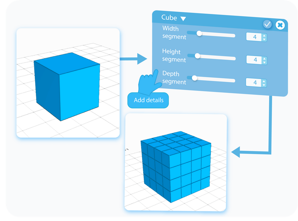
You can also customize the detail, or the resolution, of the object. Just like with the Size, the number, and names of settings dedicated to setting up the level of the detail will differ between shapes. In some cases, you will be able to change the overall resolution of the model, and in others, you will have to set the detail in all dimensions. The detail, or the resolution, adds smoothness to the figure. The more segments the object has, the more precision you're able to model with. You can edit the detail by moving the slider or by typing the values directly into the text-boxes. Unlike with the Size, the Detail has a finite value you can set, no matter if you use the slider or type the values directly.
Arc and Fill
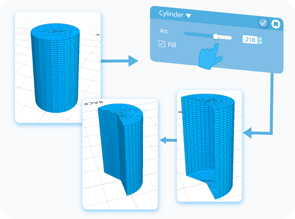
Arc setting allows you to cut a fraction of round 3D shapes, sort of like cutting a slice out of a pizza pie. The values here differ from all other settings, as you don't cut out the arc based on size, but based on the degrees of the cut. When you cut out a piece of the model, you will be left with the gap where the cut-out piece used to be. The Fill setting allows you to patch up the gap left after cutting the Arc.
Wireframe
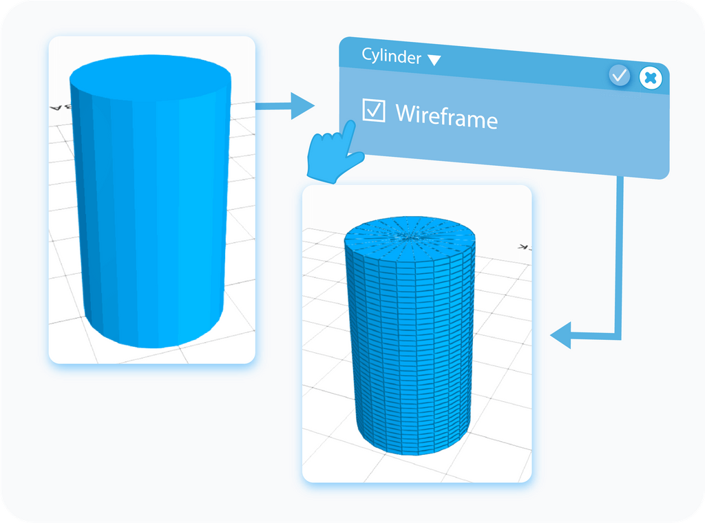
The Wireframe is an additional setting that, when enabled, allows you to see the division between individual segments of the object. It's a feature that is enabled by default so that you are able to view the changes made to the level of the Detail of the model. This setting works exactly like the Solid + Wireframe Display Mode but available during customization of your Shapes.
Hide all objects
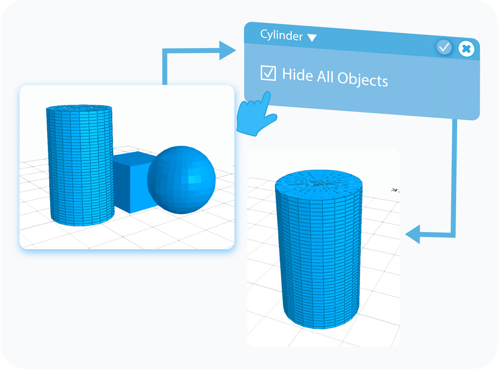
Hide all Objects is another additional setting that is enabled by default. As its name suggests, it hides every other object previously added to the grid. It allows you to customize the current 3D Shape you're working on, without other objects getting in the way. Similarly to the previous setting, Hide all Objects is available only during customization of your Shape, but you will find a similar option to Hide objects in the Display Settings.
Position
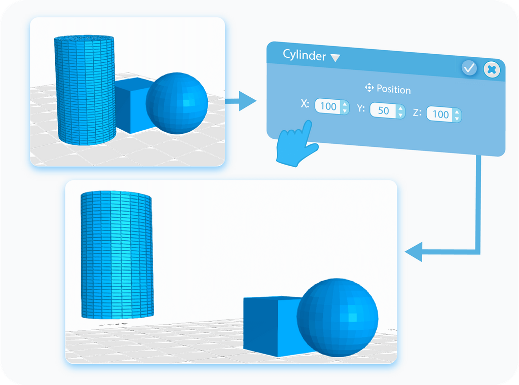
Position is one of the two settings that allows you to customize the placement of the Shape within the grid. You're able to manipulate it by changing the values in the textboxes. Each textbox represents the position on one of the three axes. You can use both positive and negative values, which will change the direction of the movement on each axis. As with all those settings, Position can be manipulated when customizing the Shape, however, you can later change it with the help of the Move tool.
Rotation
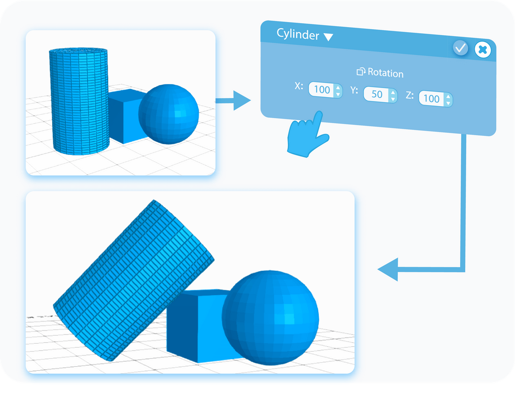
Rotation is the second setting that allows you to customize the placement of the Shape within the Grid. With this setting, you are able to set the shape's angle of rotation. Change the values in the textboxes and rotate your object to whatever angle you want on each of the three axes. You can use both positive and negative values to change the direction of the rotation around the axis. Similarly, Rotation can be manipulated when customizing the Shape, however, you can later change it with the help of the Rotate tool.
Create Bridges
You can use regional selection to create bridges between them. In the following examples, you can see how to create them between Edges, as well as Polygons.
Boolean
With the Boolean operations, in SelfCAD called Stitch & Scoop, you can use various shapes to impact other models.
And that's all there is to the basic 3D shapes. After reading this article, you should have the general idea behind 3D shapes and know how to customize your objects using all of the described settings, as well as some of the tricks that you can use them for. Of course, the graphics shown here were just examples. There are just so many shapes that it would take forever to cover each one of them and to showcase all of those settings in action. The underlying principles will always stay the same, no matter the Shape, so you should be fine experimenting with them on your own. So, what are you waiting for? Go and make something awesome!
Haven't tried SelfCAD yet? Register now, and try it out for free!

Do you want to learn 3D modeling? Check out our interactive tutorials.


