Move Tool
Table of contents:
Introduction
Move
Move a region
Additional Settings
Advanced Settings
Hello!
In this article, we are going to learn about SelfCAD's Move tool. I am going to explain all of the ins and outs of this feature, as well as present its applications. Move is one of the basic transformation tools available in SelfCAD, and you can find it in the main Toolbar, right next to the Drawing tools. As its name suggests, it allows you to move selected objects or selected regions of the object around the grid (workspace). On top of that, Move has a few options that stand out from the competition. Different modes of operation, as well as the Magnet, are all unique to SelfCAD. Follow this article to learn all about them!
Select an object
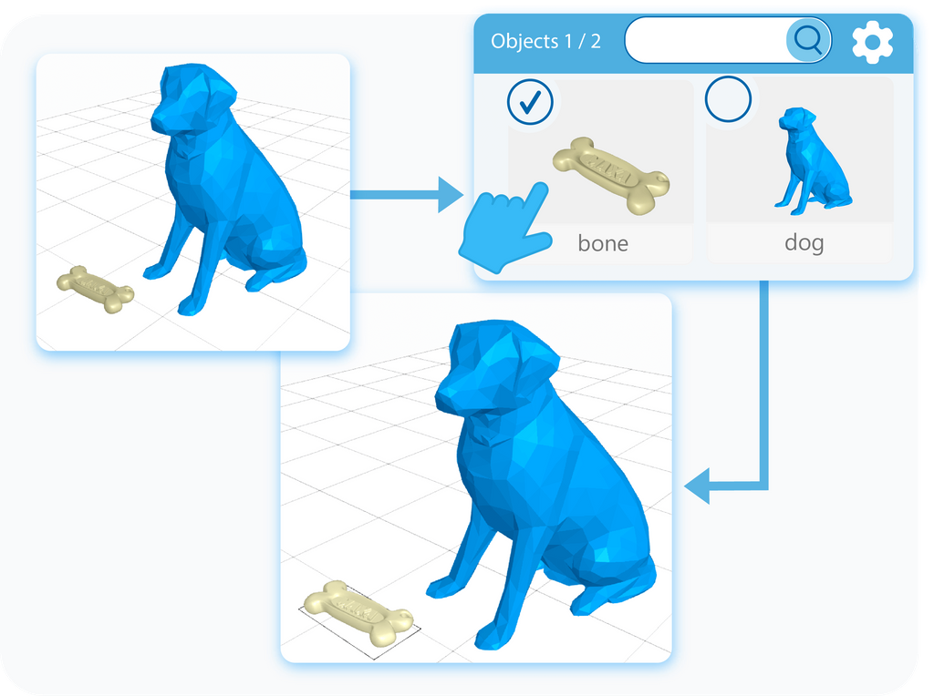
The first step of using any modeling tool is selecting the object on which you want to use it. You can select objects by either left-clicking on them in the workspace or by selecting them in the Object Management section, in the right-side panel. The second option has an in-built search engine, which is extremely useful when you are working with multiple objects.
Activate the tool
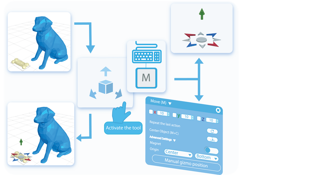
Once the object is selected, you can activate the Move tool by selecting it from the main toolbar, or by pressing the letter ‘M’ on your keyboard. This way, you’ll open a Tool Setting Panel with all of the customizable options for this tool on the left side of your screen. Activating the Move tool will also enable the Gizmo that you can use to move the object around.
Modes
There are two modes of operation available for the Move Tool. The first of them is called Move To, which is the default option. It will be explained in the following paragraphs, but this mode moves the object directly to the position specified by the used coordinates.
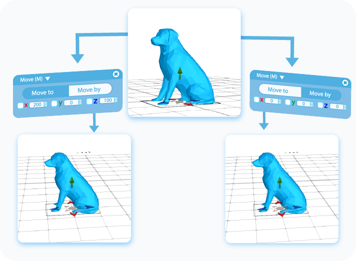
The second mode is called Move By. It moves the object by a nominated value from its original position. It is a handy feature when it comes to precise modeling when you have to move the object by using it as a point of reference.
Move
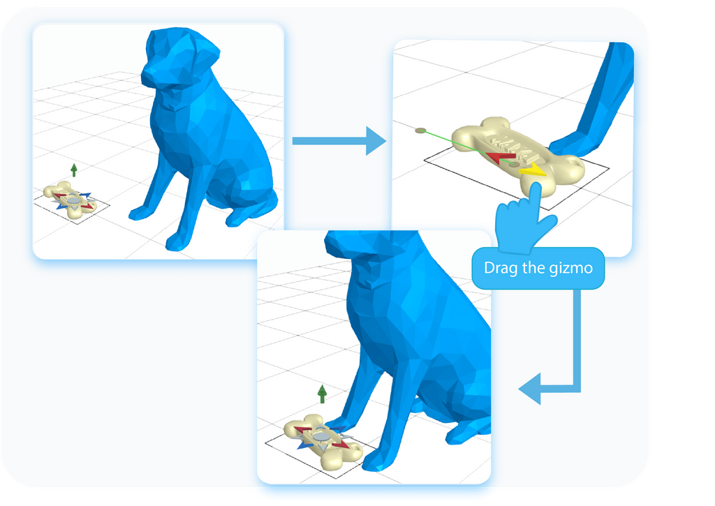
The first option to move the selected object in SelfCAD is by dragging the Gizmo mentioned in the previous paragraph. As you can see, it points in different directions, which indicate in which dimension and in which way you can move the object. Please note that you cannot move the object beyond the borders of the workspace. If you try to move it beyond them, it will snap back to it.
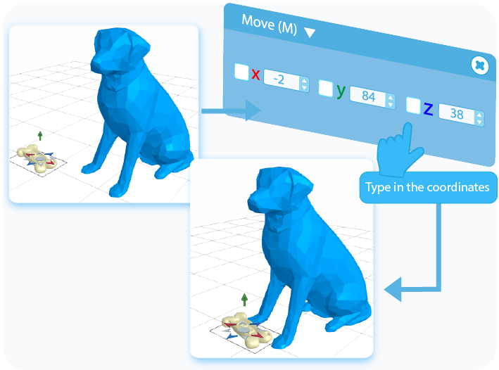
The second way to move an object is by typing the exact coordinates into the textboxes on the Tool Setting Panel. Furthermore, you can use the checkboxes to copy the same values between the text boxes. Each of them refers to the position of the object on one of the axes, whose position you can check on the 3D Coordinates Axis on the bottom right side of the grid. Just like before, if you try to move the object beyond the borders of the workspace, it will automatically snap back to it.
Select a region
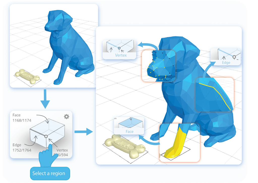
SelfCAD allows you to not only change the position of the object itself, but you can also move some of its regions. To do so, you need to select those regions first. In the Right Side Panel, you will find an Interactive Rectangle, where you can enter one of the following selection modes: Face, Vertex, and Edge. Then, you can select the parts of the object that you want to move.
Move a region
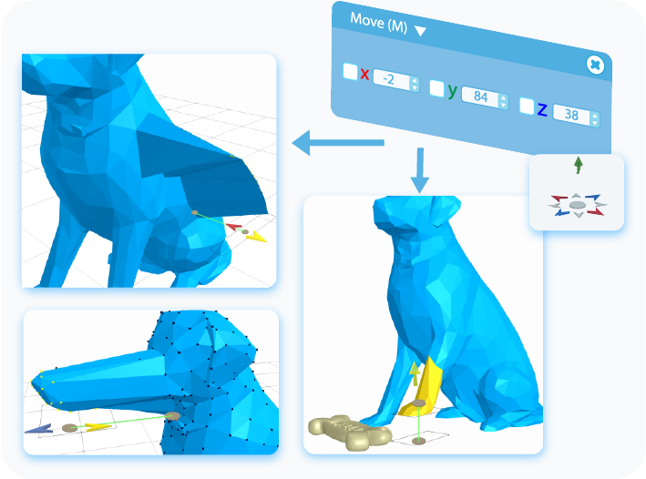
Moving a region works exactly the same as moving the object itself does. After selecting a region or regions that you want to move, you can either drag them with the help of the Gizmo or type in the coordinates into the text boxes, to move the selected region To specified coordinates or By a typed value. Just like before, you cannot move it beyond the borders of the workspace, and it will snap back when you try.
Center Object
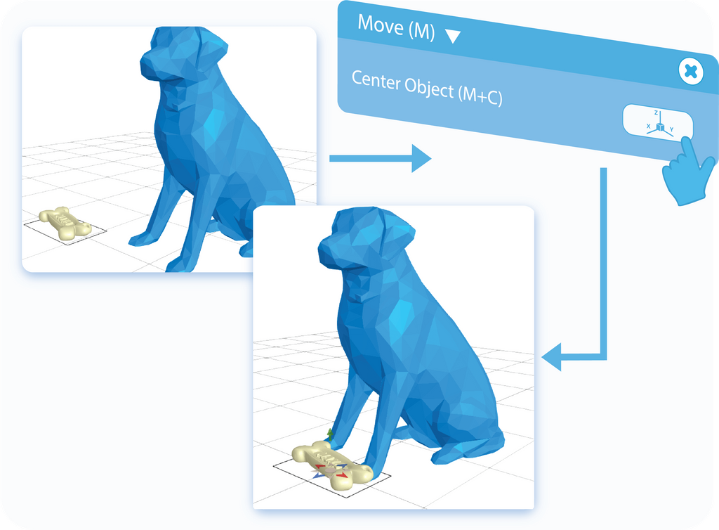
Below the coordinates in the Tool Settings, you'll find the option called Center Object. The feature is rather self-explanatory: Center Object resets the position of the object and snaps it back to the center of the grid.
The Magnet
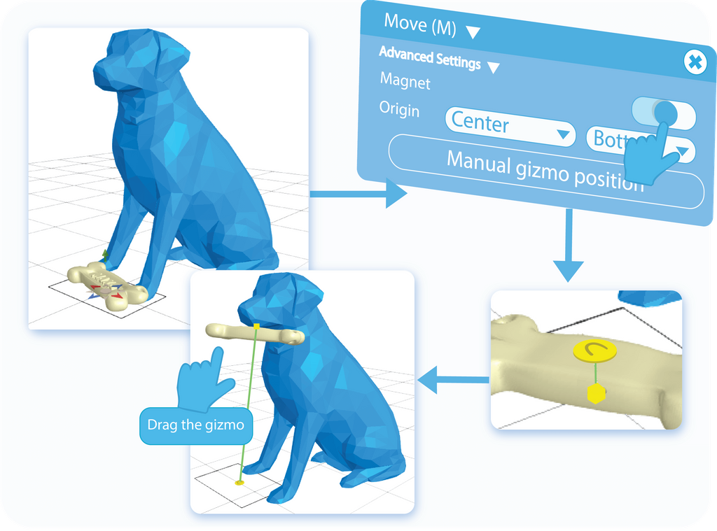
You can find the Magnet tool in the Advanced Settings of the Move tool, after expanding the drop-down list. With this feature, you can snap the object to any surface and have it cling to this surface as if it was pulled by the magnet.
The Magnet - Origin
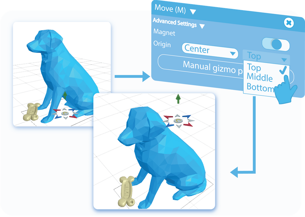
Below the Magnet, you will find the option to set the origin of this feature. You can use one of the preset options in the dropdown list, or use the Manual Gizmo Position feature to set the point of origin manually. In practice, the Magnet allows you to choose which point of the object will snap to another.
Local Transformation
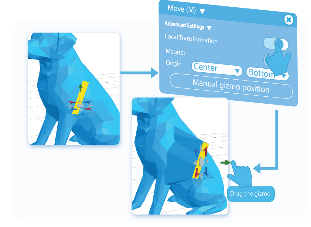
Local Transformation is another feature available in the Advanced Settings of the Move tool, and it is available only when you are moving a region of the object. By enabling this option, you will Move and rotate the position of the Gizmo, which in turn will allow you to move the region independently from the rest of the model. To use this option, you have to enter a specific Selection Mode, and then select the region of the object that you want to move. You can go back to Select and Move a region paragraphs for a more detailed explanation.
Minimum Step Size
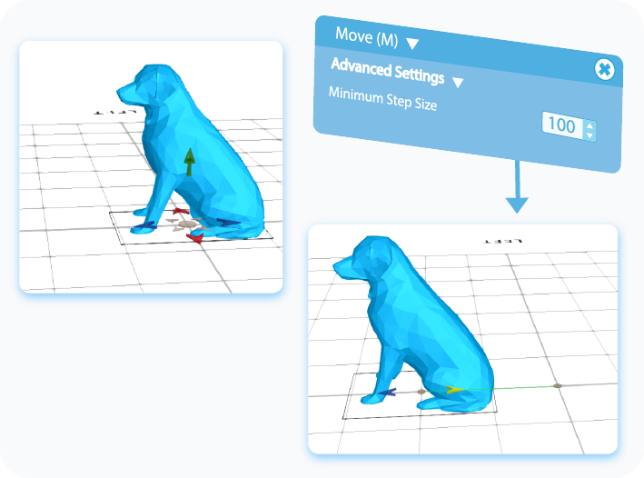
Minimum Step Size is one of the most useful features when it comes to precise modeling, and you have to operate on strict values. It locks the tool at a specified value, and it will move the object by the multiplication of this value. For example, if you set this feature to 100, then you will move the object for 100 units in any direction, which will be the first step. When you try to move it further, it will do so by another 100 and so on.
That’s about all there is to the Move feature. After reading this article, you should know the basics of the Move tool and how to use it, know about its different applications and how to implement and customize its advanced settings using the magnet. Of course, the graphics shown here were just examples, and using this tool on other shapes will give you slightly different effects, but its underlying principles will always stay the same.
That's all I have for you today. I wish you success in your future projects. See you, and stay tuned for more content to come!
Haven't tried SelfCAD yet? Register now, and try it out for free!

Do you want to learn 3D modeling? Check out our interactive tutorials.


