3D Shapes: Gear Generator
Table of contents:
Introduction
Adding Shapes
Additional Settings
Customizing Shapes
Customizing Placement
Tips & Tricks
Welcome to the article dedicated to SelfCAD's 3d modeling tool called 3D Shapes. In this article, I'm going to explain the process of creating and customizing shapes with the help of the Gear Generator. 3D Shapes can be found in the main Toolbar, and as you can see, Shapes in this category have been divided into two sections: basic and advanced. Gear has been placed in the section below the divider, which marks it as one of the more complex shapes available in SelfCAD. Because of its complexity, the customization process is much more complicated than it was in the case of basic shapes.
Adding shapes
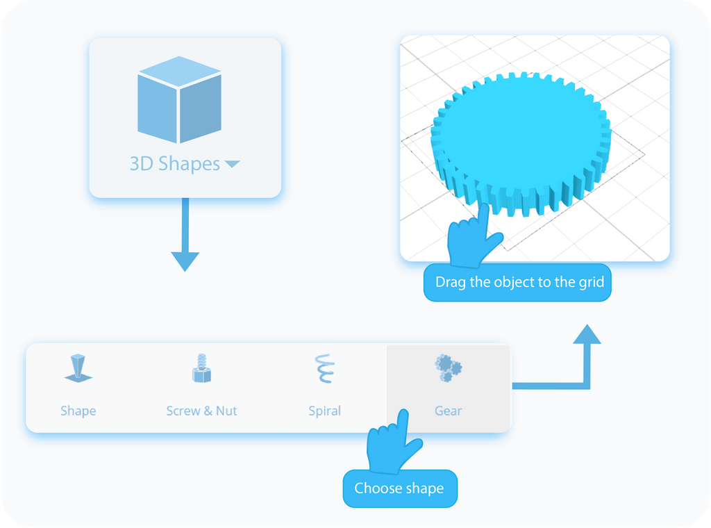
Let's start with adding Gear to the workspace. There are two ways to do that. The first option is to simply select it from the drop-down list and drag it to any place on the grid. It's the quickest way to add shapes, but the downside of this method is that your Gear will be created with its default 3D properties, and it will skip the customization process unique to the selected model.
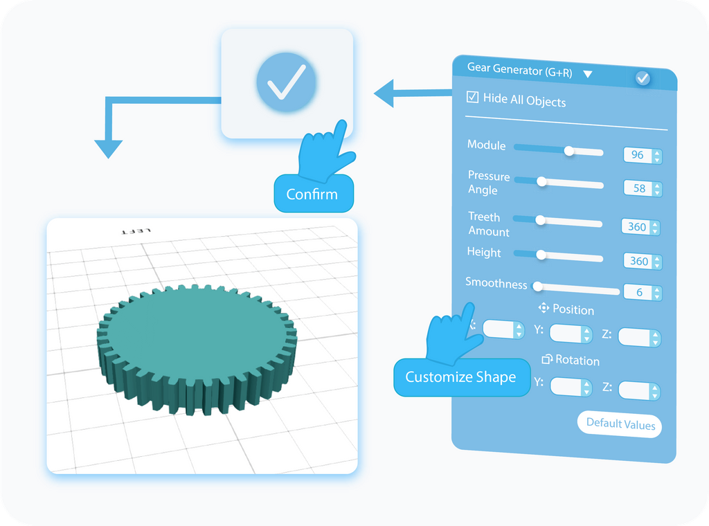
The second way to add Gear to the workspace is by clicking on it in the drop-down list. By doing so, you will open the Tool Settings panel on the left side of the screen, which will contain all of the unique settings available for the Gear Generator. Contrary to the previous method, here you can customize your Shape even before it will be added to the grid. You can set here the properties such as size, pressure angle, teeth amount, position, and rotation. It's important to note that once you finish this process, you won't be able to get back to those settings. Of course, you will still be able to modify your shape with the help of other tools, but the settings explained in this article can be accessed only when adding new Gear.
Hide all objects
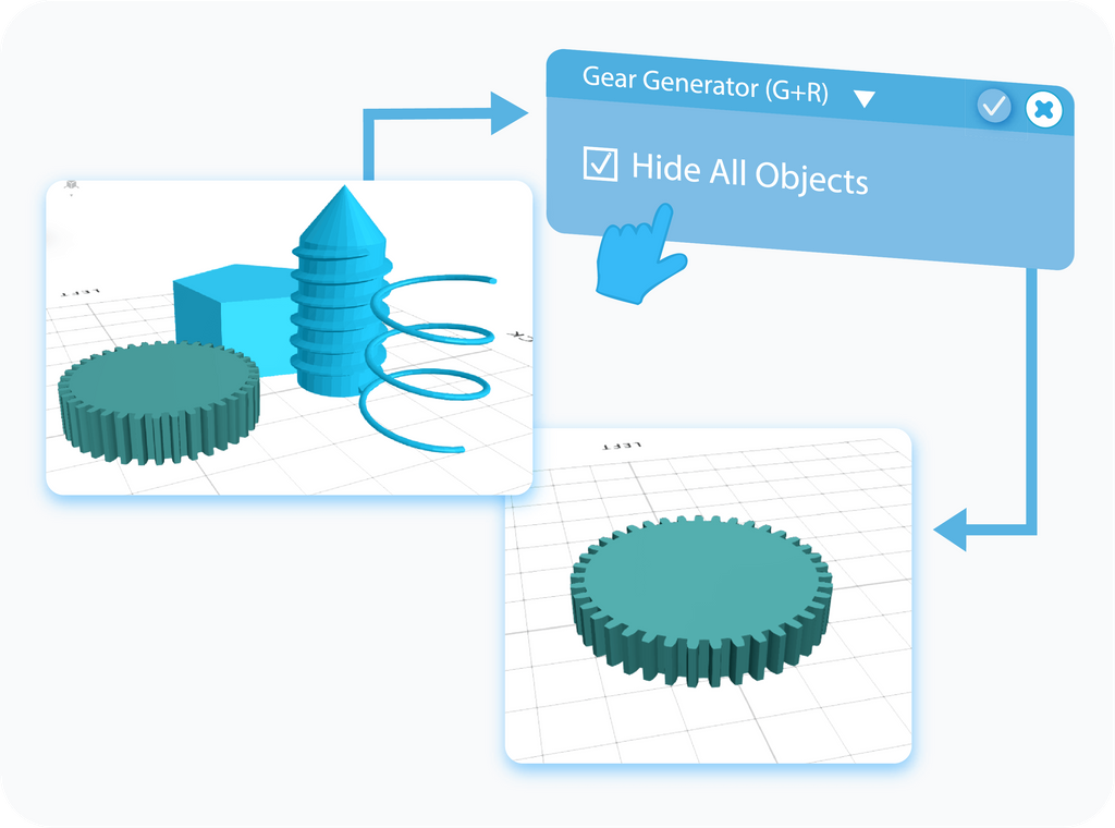
Hide all Objects is another additional setting that is enabled by default. As its name suggests, it hides every other object previously added to the grid. It allows you to customize the current 3D Shape you're working on, without other objects getting in the way. Similarly to the previous setting, Hide all Objects is available only during customization of your Shape, but you will find a similar option to Hide objects in the Display Settings.
Module
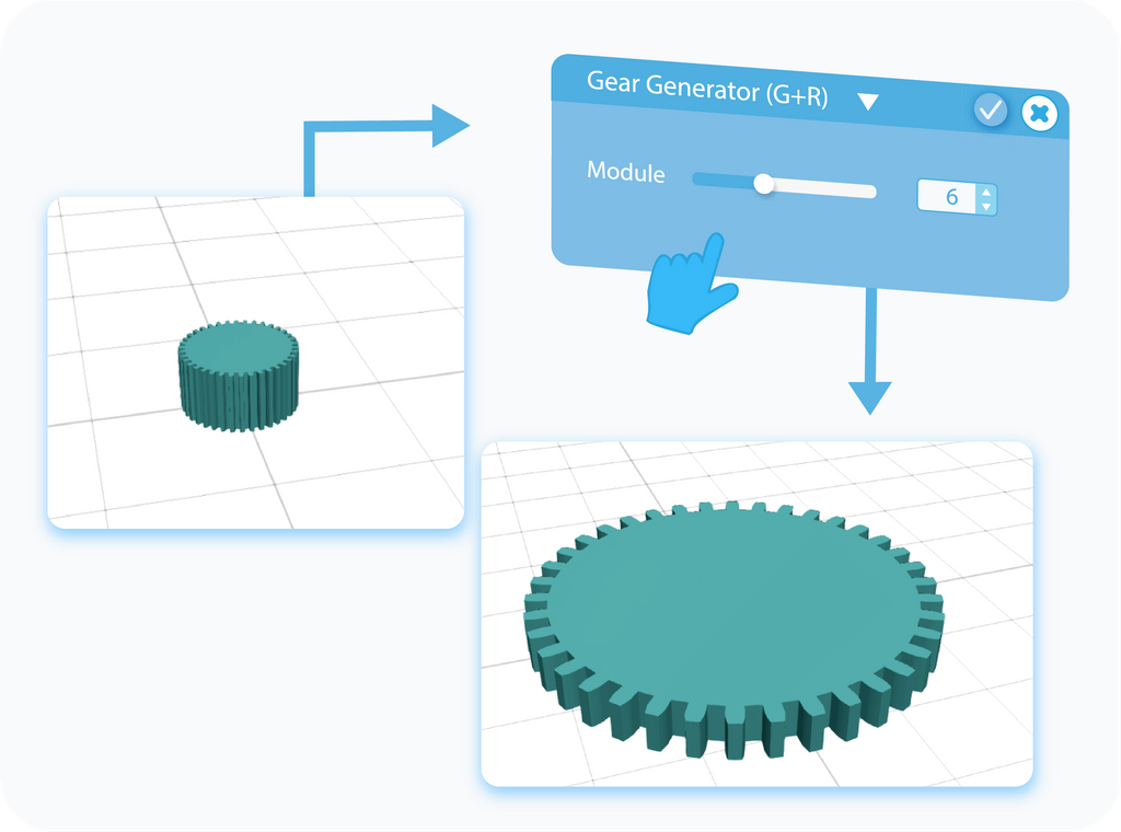
Module setting allows you the set the overall size of the Gear. It allows you to set its diameter, and indirectly, the size of its teeth, as they will have to adjust their size to fit around it. Please note that it's the main setting when it comes to size, but there are other settings that will impact its size as well. You can choose the object's dimensions by either moving the slider to manipulate the values or by typing the values directly into the textboxes. It's important to note that in the case of the Advanced Shapes you're more restricted in terms of customization than it was the case in Basic Shapes, and you can't scale the object beyond what is possible with the slider.
Pressure angle
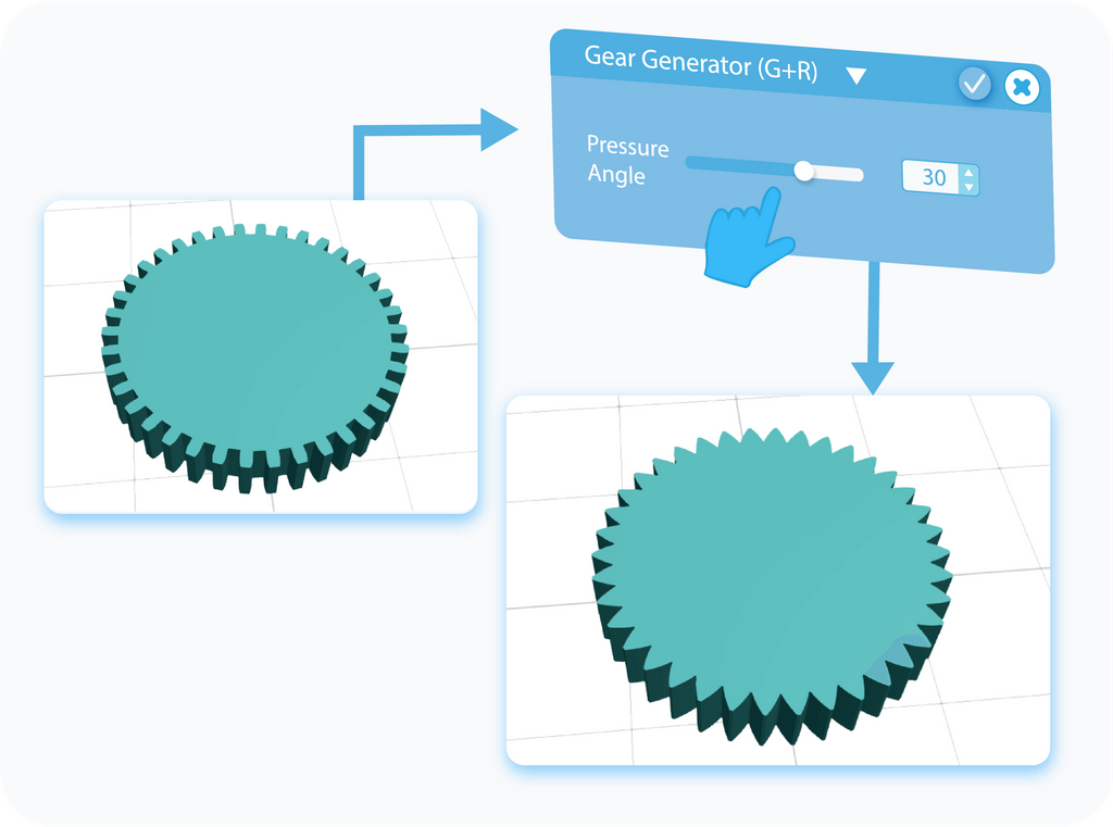
Pressure Angle is another setting that changes the shape of the Gear, and more precisely, its Teeth. It allows you to change their shape, and indirectly, their length. Lower values will make the Teeth very edgy, while the higher you go, the more rounded they will become, and transitions between them become even. As before, you can set the values by either moving the slider to manipulate them or by typing them directly into the textboxes. Unlike with the previous setting, Pressure Angle has a finite value you can set, no matter if you use the slider or type the values directly.
Teeth amount
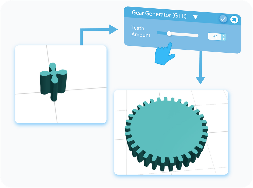
Teeth Amount is a rather self-explanatory setting. The value here directly translates into the number of teeth of the gear until it caps at one hundred. It's a setting that has an indirect impact on the size of the gear, as the higher the number of teeth, the more space they will need, which will increase its radius. Similarly to the previous setting, you can set the values by either moving the slider to manipulate them or by typing them directly into the textboxes. Teeth Amount has also a finite value you can set, no matter if you use the slider or type the values directly.
Height
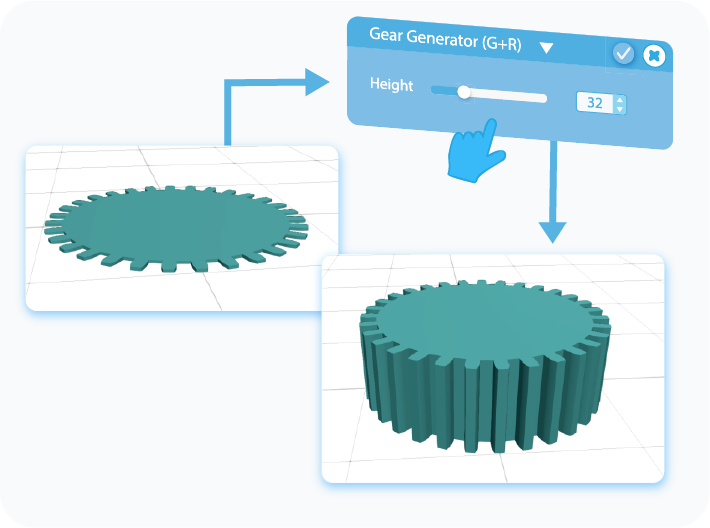
Height is a second setting directly responsible for changing the overall size of the Gear. As its name suggests, Height allows you to set the height of the gear, which is its size on the Y-axis. Contrary to the Module, there are no other features that would indirectly change the height of the Gear. You can set its values by either moving the slider to manipulate the Height or by typing the value directly into the textbox. It has also a finite value you can set, no matter if you use the slider or type the values directly.
Smoothness
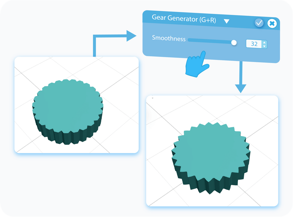
Smoothness allows you to customize the detail, or the resolution, of the Gear. The more segments it has, the more precision you're able to model with. You can edit the detail by moving the slider or by typing the values directly into the text-boxes. Similarly to other options of the Gear, Smoothness has a finite value you can set, no matter if you use the slider to change it or type the values directly.
Position
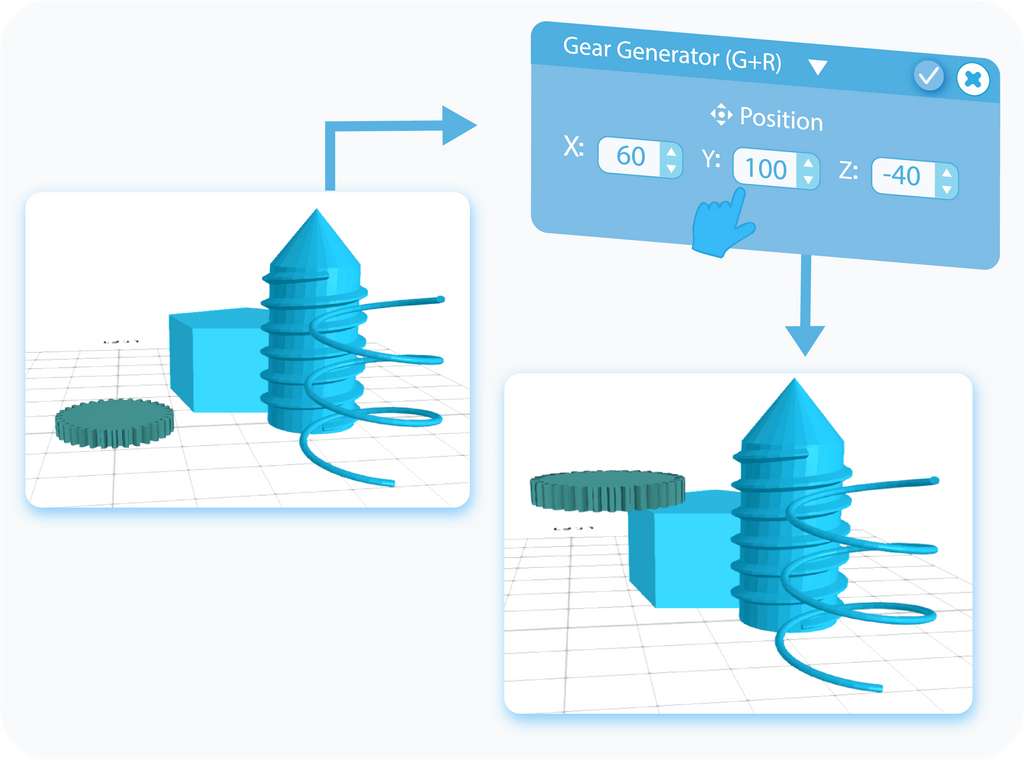
Position is one of the two settings that allow you to customize the placement of the Gear within the grid. You're able to manipulate it by changing the values in the textboxes. Each textbox represents the position on one of the three axes. You can use both positive and negative values, which will change the direction of the movement on each axis. As with all those settings, Position can be manipulated when customizing the Gear, however, you can later change it with the help of the Move tool.
Rotation
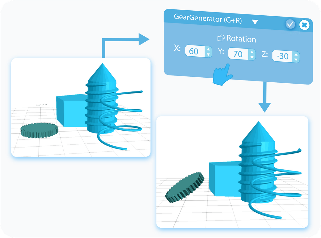
Rotation is the second setting that allows you to customize the placement of the Gear within the Grid. With this setting, you can set its angle of rotation. Change the values in the textboxes and rotate your object to whatever angle you want on each of the three axes. You can use both positive and negative values to change the direction of the rotation around the axis. Similarly, Rotation can be manipulated when customizing the Gear, however, you can later change it with the help of the Rotate tool.
Create Bridges
You can use regional selection to create bridges between them. In the following examples, you can see how to create them between Edges, as well as Polygons.
Boolean
With the Boolean operations, in SelfCAD called Stitch & Scoop, you can use various shapes to impact other models.
And that's all there is to the Gear Generator. After reading this article, you should have a general idea about its creation and the customization process behind it, as well as some of the tricks that you can use them for. Of course, the graphics shown here were just examples, and any change in the settings will impact the overall shape of the object, but their underlying principles will always stay the same. And that's all I had for you. I wish you success in your future projects. See you, and stay tuned for more content to come!
Haven't tried SelfCAD yet? Register now, and try it out for free!

Do you want to learn 3D modeling? Check out our interactive tutorials.


