
Create a Robotic Arm Prototype with SelfCAD AI
A robotic arm prototype is normally built by designing individual components such as the base, arm segments, joints, gripper, and connecting supports before putting them together into a full construction. With SelfCAD AI Modeling, you may create a preliminary 3D model based on your thoughts and describe your robotic arm design in natural language.
SelfCAD AI Modeling can enable a variety of 3D designs, including mechanical components and functional assemblies. Once the robotic arm prototype is created, you can examine, adjust, and improve the arm segments, joint locations, gripper design, and mounting structures using SelfCAD's standard modeling tools. You can create a detailed mechanical model that is appropriate for educational displays, prototyping, or 3D printing by modifying the size, proportions, and connections.
Design a Robotic Arm Prototype with SelfCAD AI Modeling
Using a base, arm segments, joints, a gripper, and other mechanical parts, this guide will show how to build a robotic arm prototype. An essential AI modeling principle is highlighted by the process for educational demonstrations, prototyping, or 3D printing: the more accurately you describe the arm dimensions, joint positions, segment proportions, connection points, gripper design, and mounting structure, the more closely the generated 3D model will match your intended robotic arm design.
Step 1: Open SelfCAD Editor
Start by creating a new project in the SelfCAD Editor.
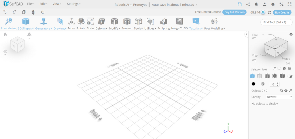
You will create the first shape of a robotic arm prototype for this project using AI modeling. The base, arm segments, joints, gripper, and connecting parts will all be supported by the AI-generated design. Use the conventional modeling tools in SelfCAD to modify the dimensions, strengthen the joint connections, align the arm segments, and enhance the overall structure after generation in order to get the required mechanical appearance.
Step 2: Open AI Modeling.
Choose the SelfCAD Editor's AI Modeling option.
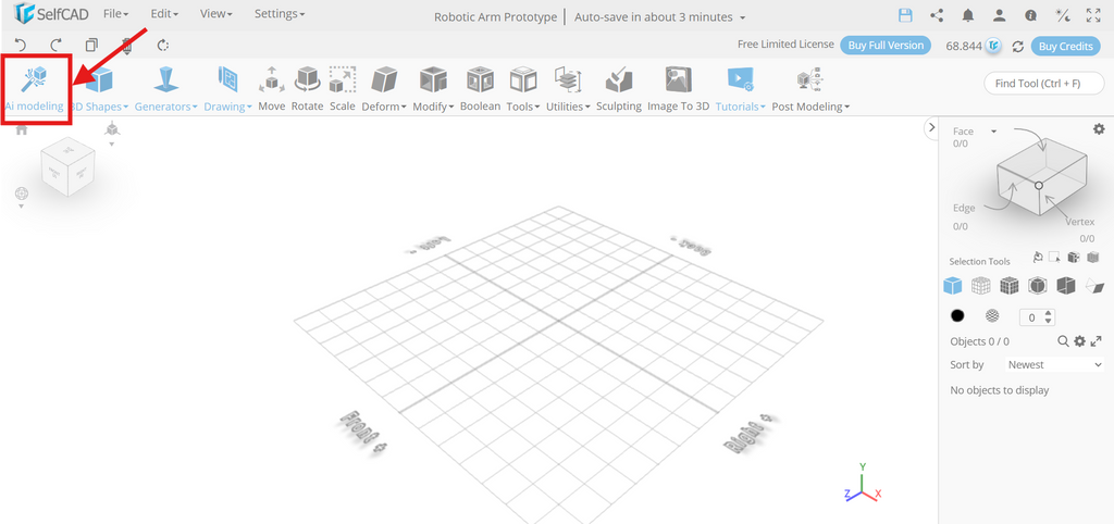
Describe the robotic arm prototype you wish to build using the text prompt form. To enable a range of 3D designs, SelfCAD provides many AI modeling techniques.
Instead of creating an ornamental item or organic sculpture, the project's objective is to create a mechanical prototype. Give a detailed description of the base, arm segments, joints, gripper, mounting supports, and connecting parts. To assist the AI in creating a preliminary model that corresponds with your planned robotic arm concept, you may additionally define the dimensions, segment lengths, joint positions, connection points, and gripper design.
Step 3: Select the appropriate creation mode
Select the creation mode that works best for your prototype robotic arm. Choose Functional Assembly to arrange the base, arm segments, joints, and gripper in accordance with your chosen design because this project comprises several interconnected mechanical components.
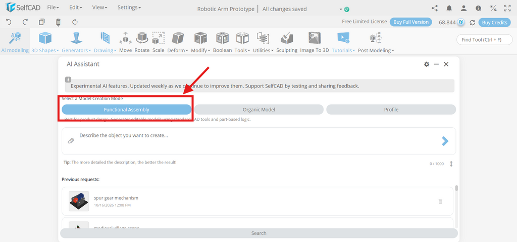
A base, rotating joints, connecting connections, a gripper, and mounting supports are possible components of the robotic arm. Explain how these parts should be arranged and joined to create a seamless assembly. In order to refine segment size, joint alignment, connection locations, and mechanical features in SelfCAD, a clear prompt aids the AI in comprehending the general structure and interactions between the parts.
Step 4: Prepare a Reference Image
Adding a reference image of a robotic arm prototype is entirely optional, although it can provide valuable visual assistance for your design. Select a picture of the base, arm segments, rotating joints, gripper, and connecting supports if you have one.
Your preferred arm configuration, component proportions, and overall structure can all be conveyed through the graphic. But rather than taking the place of your text prompt, it should enhance it. Your textual instructions are used by the AI Assistant to comprehend the design specifications and produce the first 3D model.
Step 5: Write the AI Modeling Prompt
Explain the robotic arm prototype you wish to build with SelfCAD AI Modeling. Add the gripper, mounting supports, joints, arm segments, base, and connecting parts. To create a cohesive mechanical assembly, identify each part's dimensions, segment lengths, joint positions, alignment, and placement. You can also include additional design features and structural supports. A clear prompt generates an initial model that may be further developed using SelfCAD's standard modeling tools.
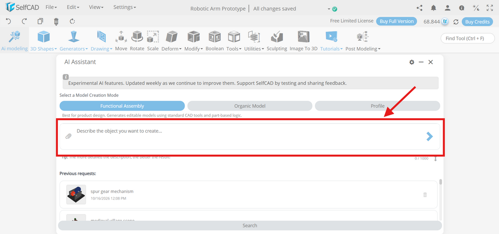
You can use the following prompt, as an example:
Prompt: Design a robotic arm prototype using AI modeling. Create a mechanical arm with a sturdy base, a rotating platform, an upper arm, a forearm, and a gripping claw at the end. Include joint housings at the shoulder, elbow, and wrist to represent rotational movement between the sections. Add cylindrical connectors, mounting brackets, and visible mechanical details to give the model a realistic robotic appearance. Design the gripper with two opposing fingers capable of holding small objects. Ensure that the arm sections are properly aligned, the joints connect securely, and the base provides sufficient stability. Use functional assembly mode to generate the base, arm segments, joints, and gripper as separate components for easier modification and assembly. Maintain balanced proportions, clean geometry, and adequate thickness for potential 3D printing. After generation, inspect the model from multiple angles and refine the joint positions, component dimensions, and connections using editing tools. Treat the model as a conceptual prototype rather than a tested, working robot.
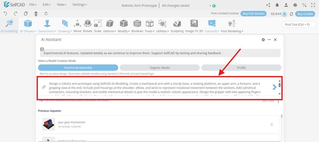
This thorough explanation makes the initial 3D model more logical by assisting the AI in comprehending the planned robotic arm layout, component proportions, joint configurations, and linkages between individual elements.
Step 6: Generate the Model
Click Generate after entering your prompt and, if you'd like, uploading a reference image to start building the robotic arm prototype.
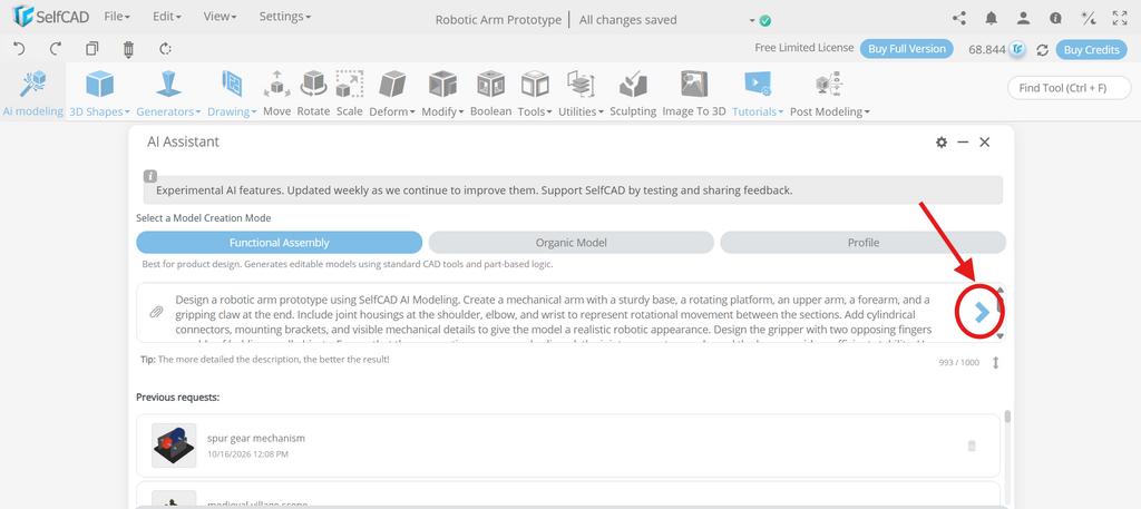
Based on your description, SelfCAD AI Modeling will decipher your instructions and create a preliminary 3D model that includes the base, arm segments, joints, gripper, mounting supports, and other mechanical parts.
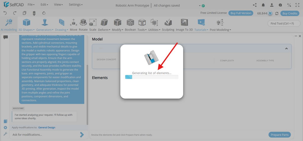
This is where manual modeling and AI-assisted modeling differ. You define your planned robotic arm and let the AI create the initial geometry rather than building each component separately from simple shapes. After that, you may review the outcomes, pinpoint areas that need work, and enhance the prototype using more AI instructions and the conventional modeling tools in SelfCAD.
Ask for Modification:
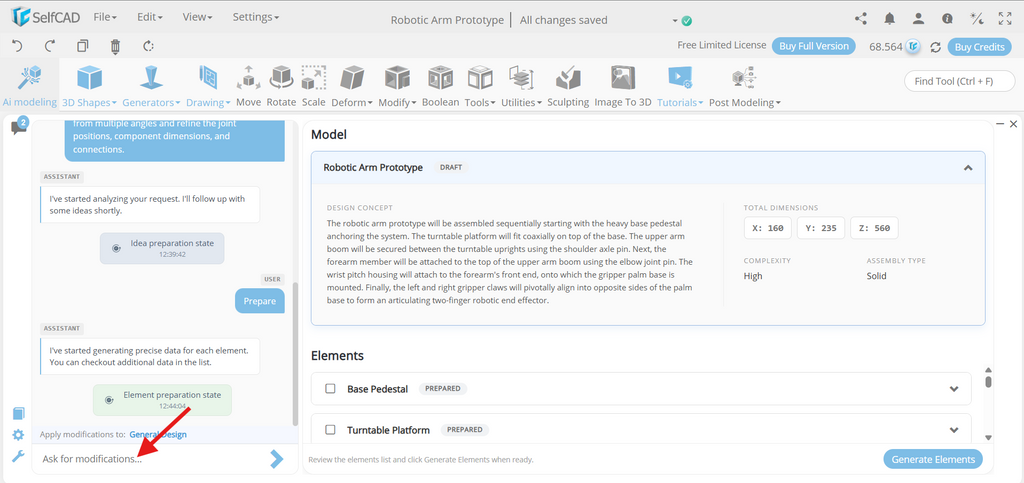
After the robotic arm prototype is created, you may utilize AI to alter the design to suit your needs. Describe the intended modifications, such as strengthening mounting supports, moving the gripper, changing joint positions, or resizing arm segments. By altering specific components in accordance with your directions, the AI can assist in improving component proportions, spacing, and alignment. You can improve the model and get your robotic arm prototype closer to your desired mechanical design by using this iterative method.
Step 7: Prepare Parts.
Both a design concept and a draft of the components will be produced by the AI assistant.
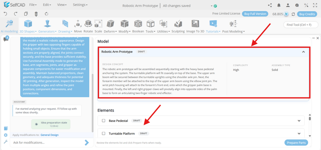
Click "prepare parts" now:
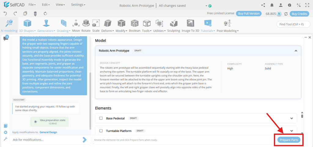
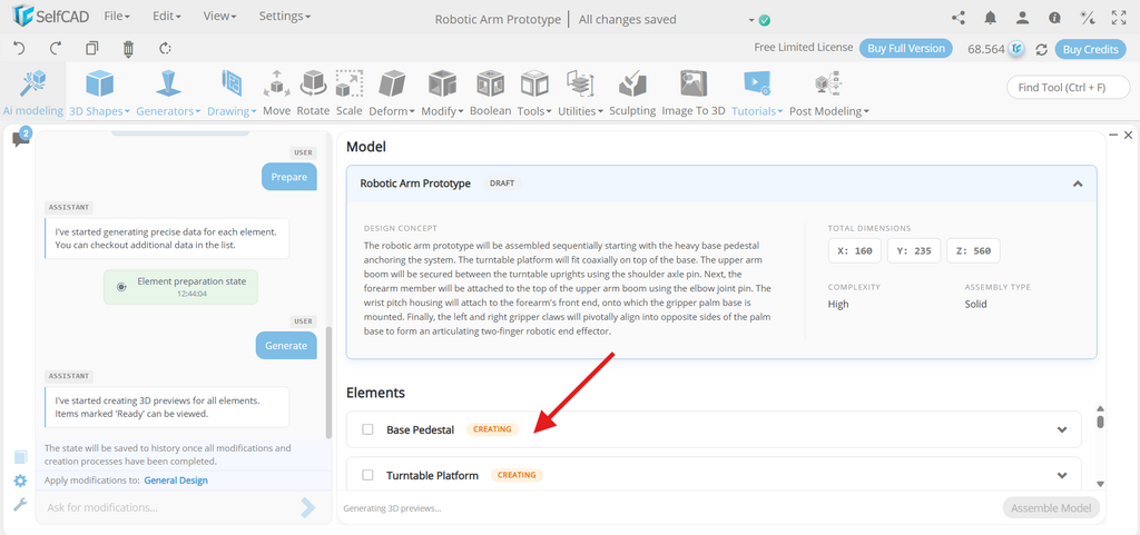
As we can see, the tool is preparing the elements:
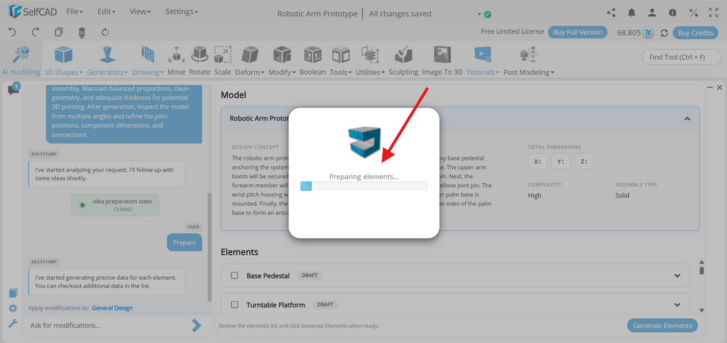
Step 8: Generate elements
SelfCAD AI offers a design overview of the robotic arm prototype, including its concept, overall size, complexity, and manner of assembly, prior to producing the geometry. Make sure these elements align with the design you have in mind.
The base, arm segments, joints, gripper, mounting supports, and connecting elements are all mentioned separately. Choose the parts that satisfy your mechanical design specifications.
Click Generate Elements to construct the individual components after you've reviewed your choices. These components will serve as the basis for your robotic arm prototype, enabling you to organize, alter, and improve the design in the subsequent stages.
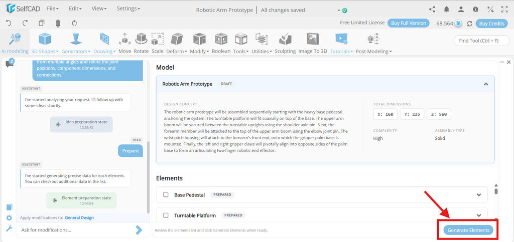
The tool will show the Creating Elements status as SelfCAD AI creates the robotic arm prototype's chosen components. After the procedure is finished, examine the pieces that were produced, such as the base, arm segments, joints, and gripper, and get them ready for additional assembly, modification, and improvement.
Step 9: Assemble Model
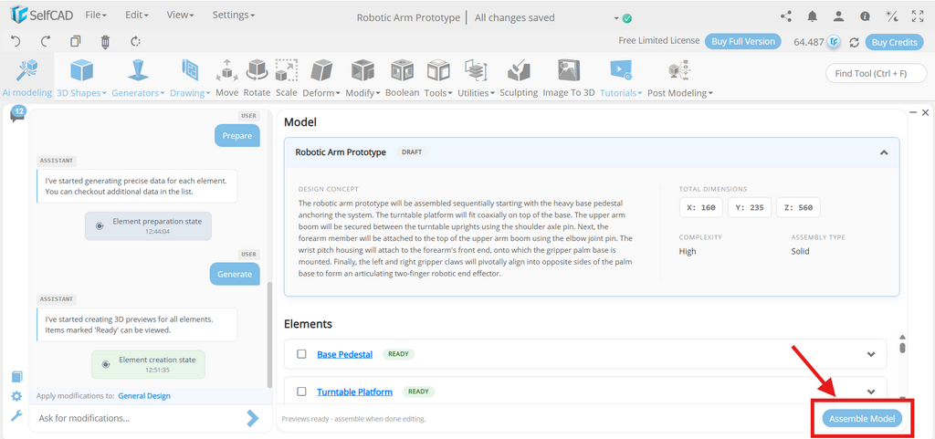
Click Assemble Model once the robotic arm prototype's created parts are complete. A full mechanical assembly comprising the base, arm segments, joints, gripper, and connecting supports will be created by SelfCAD arranging the chosen components in accordance with the intended design.
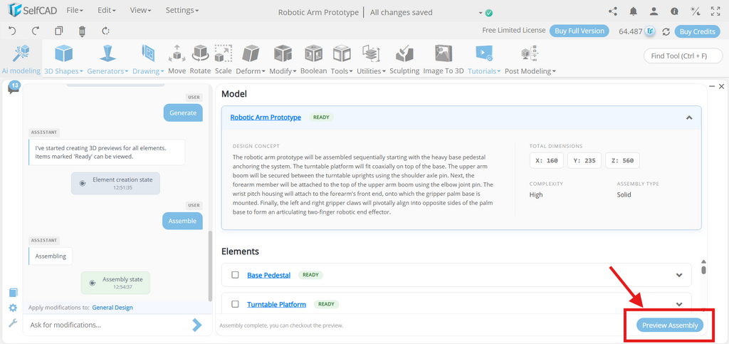
SelfCAD will assemble the created pieces to create the robotic arm once you click Assemble Model. Before making any more changes, select Preview Assembly to examine the finished design and confirm the locations, alignment, dimensions, and connections of the arm segments and joints.
Step 10: Add the Robotic Arm Prototype to the SelfCAD Scene
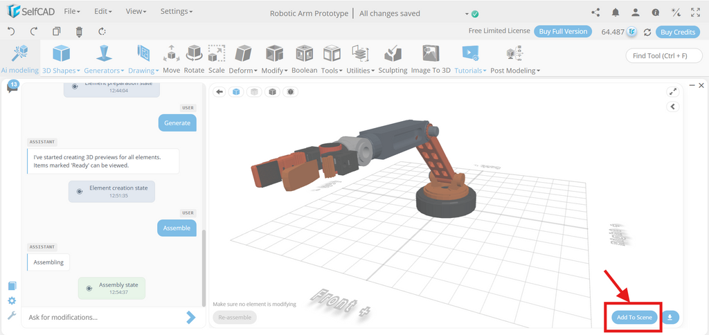
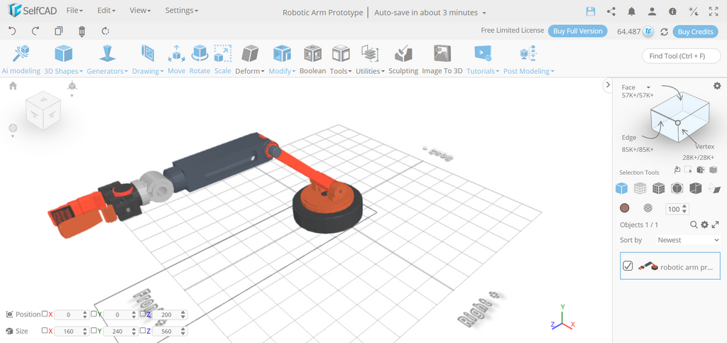
After the robotic arm prototype has been assembled, place it in the SelfCAD scene. The AI-generated design is then transferred into the usual SelfCAD workspace, where you may use conventional modeling tools to continue altering and improving the mechanical assembly. To find places that need improvement, examine the base, arm segments, joint positions, gripper, and mounting supports. To get a more precise arrangement, change the proportions, spacing, and size of the components. Additionally, you can alter individual components and improve the overall appearance of the robotic arm prototype for instructional demonstrations, prototyping, or 3D printing with features like Move, Rotate, Scale, and Stitch & Scoop.
Final Model:
Conclusion
SelfCAD AI Modeling converts written descriptions into an initial 3D model, making the design of robotic arm prototypes easier. After creating the base, arm segments, joints, gripper, and connecting parts, users can alter how they are arranged and look. The produced model can be modified into a detailed mechanical assembly appropriate for 3D printing, prototyping, or instructional demonstrations using conventional modeling tools.